This article is sharing the high level process to determine the best Drone ESC, Battery and Power Electronics setup for the S500 build with a special note on how to calculate ohm’s law or at least appreciate it! Applying power via these high capacity batteries can be dangerous, so the DIY person needs to have a healthy respect for it.
Calculate Ohm’s Law (or just don’t short the battery!)
OK, maybe you don’t need to know how to calculate it, but here is a great link to understand it completely. However, it is very important to understand what a direct short is and does between a power source’s Positive and Negative Terminals. In our case, the LiPo Battery will be powering the Drone ESC setup directly and through regulators, the controllers and receivers.
OHM’s LAW:
Voltage (V) = Current (I) multiplied by Resistance (R): V= IR
or
Current (I) = Voltage (V) divided by Resistance (R): I = V/R
It is the second of these which are important to us. It says this, the DC Current of our Li-Po Battery will go to its Maximum if the Resistance between the Positive (+) and Negative (-) is ZERO! A Dead Short is ZERO Resistance. The result, something usually burns up and pops.
Zero Resistance is easily measured via a handheld multi-meter. Here is a simple video to help if you need it: You can always Google “Measuring Continuity with a Multi-meter“.
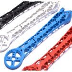
In the case of our S500 base-plate below, where we will solder our Drone ESC set, and the XT60 battery / regulator harness, we do not want a dead short anywhere it is not suppose to be. We removed the top arm set of our mechanical build to prep for this.
For Example, lets examine this image of our Un-Soldered Base-Plate and remember this:
Open: No Continuity, the multi-meter most likely reads OL.
Dead Short: Continuity exists and the multi-meter reads Zero. (putting the test leads together should read Zero.
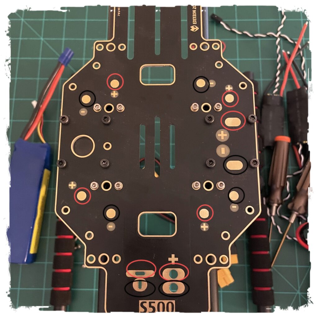
All the RED Terminals should measure continuity with each other.
All the BLACK Terminals should measure continuity with each other.
The RED and the BLACK should measure an OPEN, ie NO Continuity. (High Resistance). If it reads low resistance, try to find the short. If you cannot, do not use it.
DISCLAIMER: the above is ONLY for a bare-board with NOTHING YET Soldered to it. Once the Drone ESC setup is soldered, and/or the battery setup, these measurements are not accurate or valid.
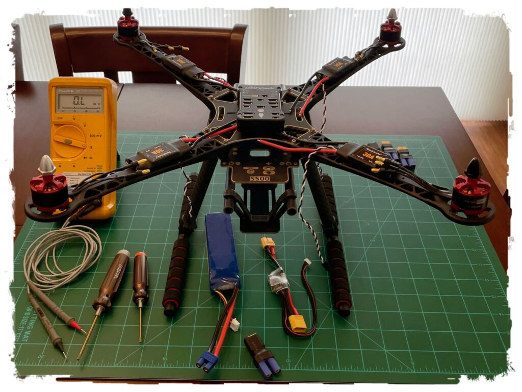
Full Frame Staged for our Drone ESC Setup
OK, the above is a bit long winded, but important. We do not want to fry our setup before we get started! So, before we begin soldering our Drone ESC package to the bare-board, we want to make sure we know which motor goes where and then take a look at wire length and fit to make sure all is well.
Clockwise vs Counter Clockwise Motors

Most drone builds mention the use of these two motor types. Don’t over think this. In reality, they are the same motor, just different threading on the shaft. The above graphic shows the direction the final configuration will spin the props.
- For the Counter Clockwise Motors (1 & 2), make sure the prop nut to secure the prop turns clockwise. Another way of looking at it, the prop nut will turn CCW to loosen.
- For the Clockwise Motors (3 & 4), the prop nut to secure will turn counterclockwise and CW to loosen.
Test Fit the wiring
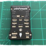
Now, with an understanding of which motor goes where, lets sit the Drone ESC package up and get an idea of the wire length, etc. Note in following image below, everything is staged for such. Though the ESC is on top of the arm, it is still in relative position to make sure the wiring will reach the solder pads on the base-plate. Note the motors are setting in their respective locations as well. The Pixhawk controller is only there as a reference.
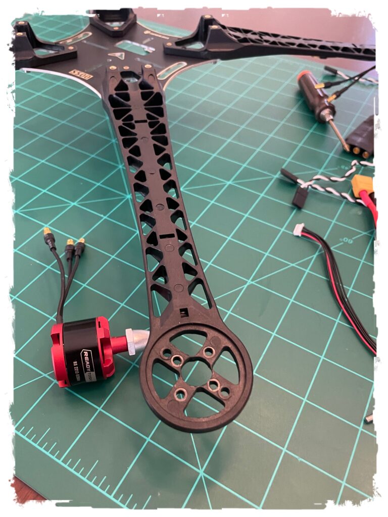
With an understanding of the fit, remove the top section and flip it upside down. Install the motors, routing the wiring as seen below. Plug in the ESC’s just to confirm the wire length will still reach past the arms. The ESC will be unplugged again during the soldering phase which is next. Here are two images to show this:
Time To Break out the Soldering Iron, Finally!
With the test fit complete, we sharpened our pencil, calculated ohm’s law, and now have high confidence we will not create a dead short situation, we can move on. Next Up, its time to solder the ESC’s to the base-plate and also the appropriate mating connector for the battery / regulator wiring harness.
We will not show a How To on Soldering. Google it if needed.
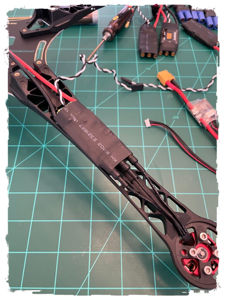
Our approach was to solder each ESC on to its pads (red wire on (+), black wire on (-) ) in such a way that we have some ‘service loop’ in the wire leads. This service loop allows for movement back and forth without stressing the joint or the wiring harness. Here is the image showing the Drone ESC setup post solder. Note the ‘service loop’.
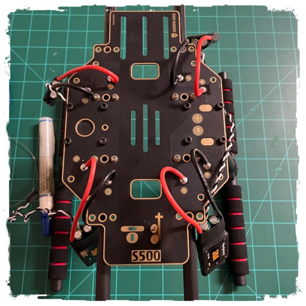
Battery Connector: Note the XT60 connector is also soldered into place in the above image. This connector will be used to connect our battery and regulator setup, which will bring power to the Drone ESC Setup.
Top Arm Assembly Placement:
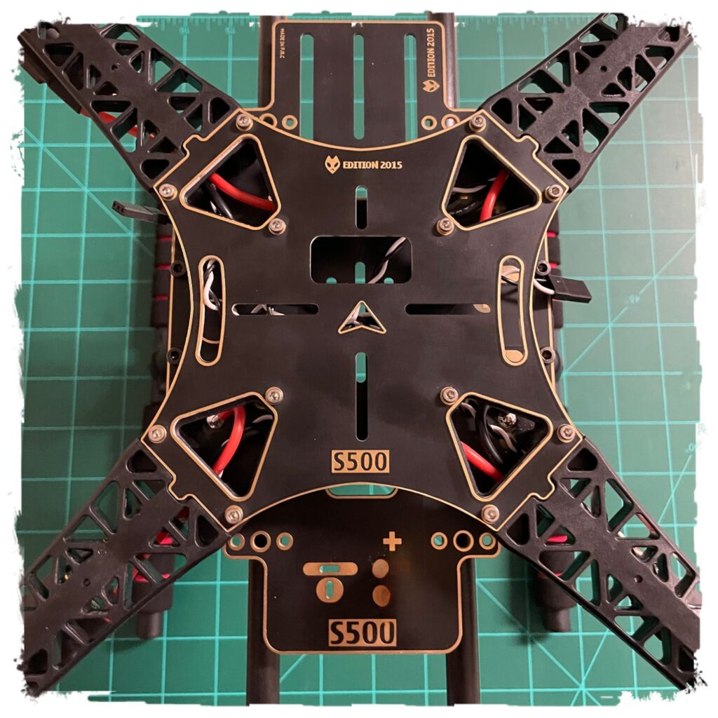
Re-Assemble the top arm assembly to the baseplate. Be careful to make sure the red/black ESC wires are inside the groove and there is plenty of ‘service loop’. Here is an image showing a top down close up of the S500 Top Arm Plate secured.
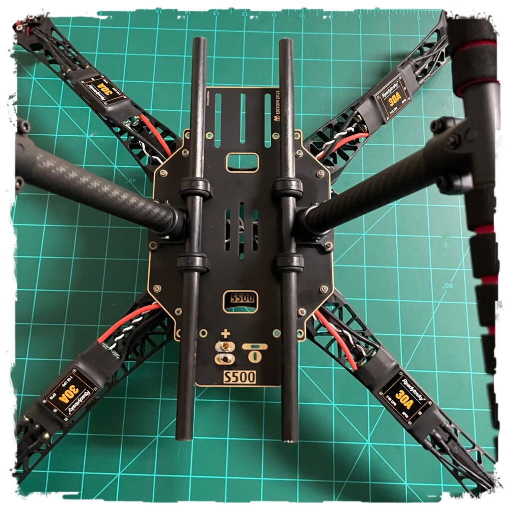
A Peek Underneath!
ESC’s and Battery Connector soldered into place and the Top Arm Assembly back on, the unit was flipped over and here is the image. From here you can see a clean assembly, the final location of the ESC’s on each ARM and how the wires channel properly through the arm groove. Note, the ESC’s were plugged back into the motor wires, however final connections will most likely change when we configure the direction of each motor at initial spin up testing.
NEXT! This portion of the build is complete. Note, we will add zip ties near the end, once the motors are spinning in the correct direction and its time to put the finishing touches on the model before it is flown! Next Up, Setting up all the electronics! Note: following the Calculate Ohm’s Law section above will save us many headaches in this next step!!
Social Media:
We share our images, video and experiences in all of the flying hobbies here. This Drone ESC Battery and Power Electronics setup post, part of the overall S500 Build and Fly documentation, will certainly be featured!